 |
ME 305 Group 6 Documentation
|
|
ME 305 Group 6 Documentation
|
This page contains information about the Term Project.
The goal of this project is to actively balance a steel ball on the platform pictured below.
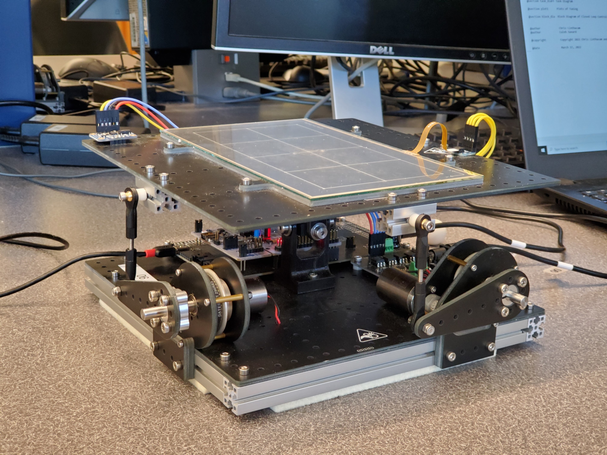
The platform is equipped with an IMU, a 4-wire resistive touch panel. These sensors measure the angle and angular of the platform, and position of the ball. A video of the device's operation can be seen below.
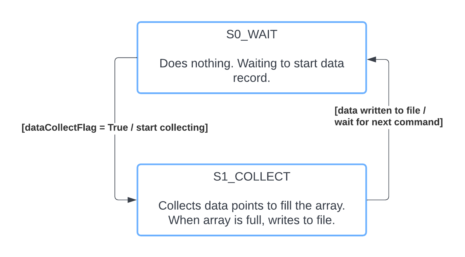
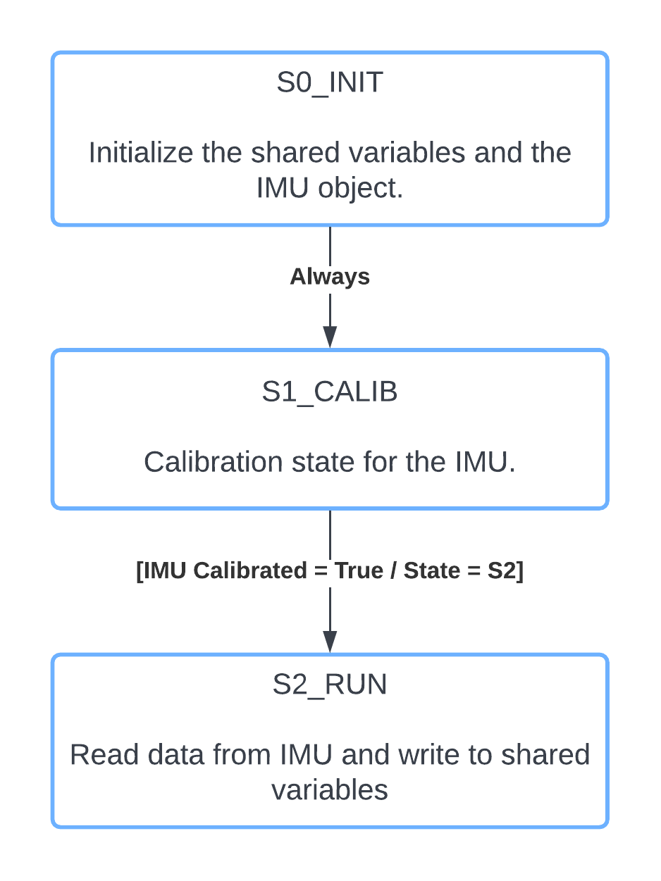
The system is primarily controlled by the User task. This handles user input for the various parameters by assigning values to 'flag' variables - Shares objects which are read within other tasks to trigger responses. The user task also handles printing of values written to the print queue. The IMU task (taskIMU.py) creates, calibrates, and reads an IMU object. The touch panel task (taskPanel.py) creates, calibrates, and reads the touch panel. One X-Y scan of the touch panel runs in 630 μs, as detailed in the touch panel page. The angle controller task (taskAngleController.py) takes the position of the ball and returns a desired platform angle to keep the ball balanced. This desired angle is fed into the motor controller task (taskMotorController.py), which attempts to set the platform to that angle. Both of these controller tasks use a seperate controller object (closedloop.py) for the X and Y direction, and the angle controller supports seperate gain values for the each direction. The data collection task (taskDataCollect.py) collects data from the device and writes it to a file.
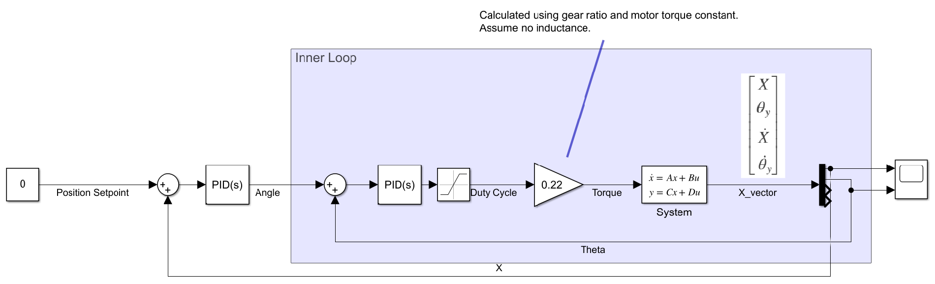
Using the results of Homework 3 (homework_3.html), we attempted to create a simulation to help tune the system. This proved unsuccessful as the values given for Homework 3 did not seem to match the real system characteristics. The simulation did, however, allow us to gain a more intuitive understanding of the tuneing process from repeated experimentation. The block diagram for the system can be seen below. The functions inside the function blocks come from Homework 3 and can be viewed there.
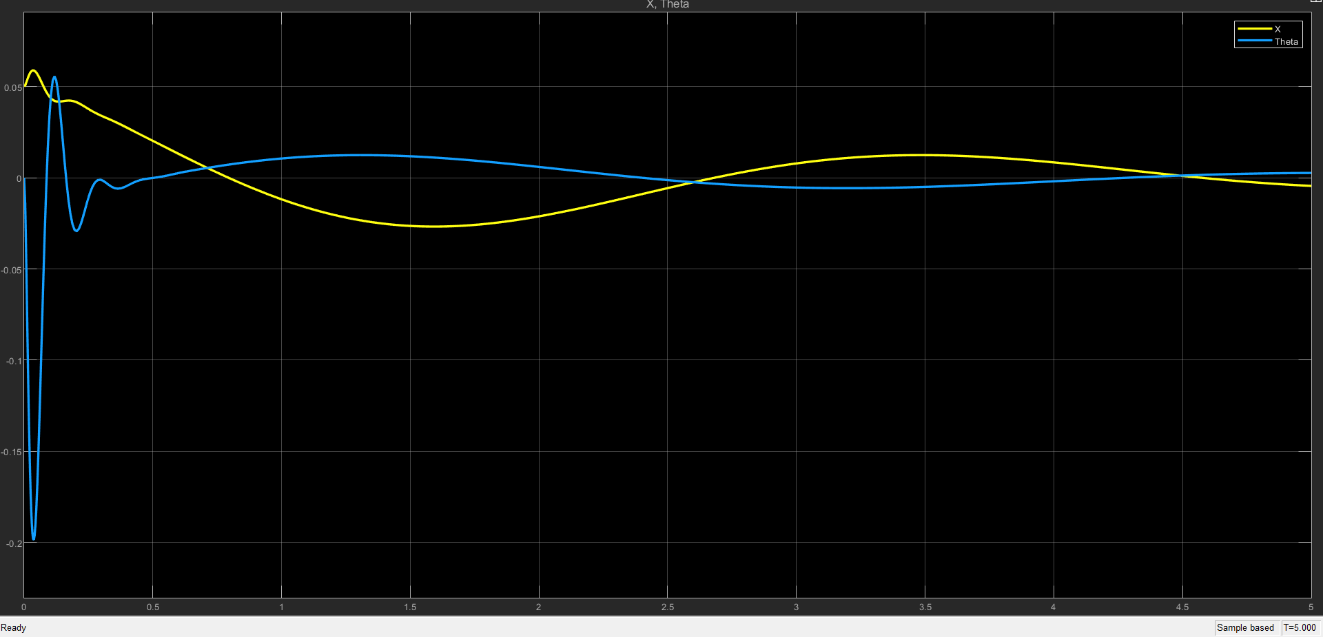
The following plot for a single axis was developed using gains for the inner loop of Kp = 6, Kd = 0.2, and for the outer loop, Kp = 0.5, Kd = 0.1.
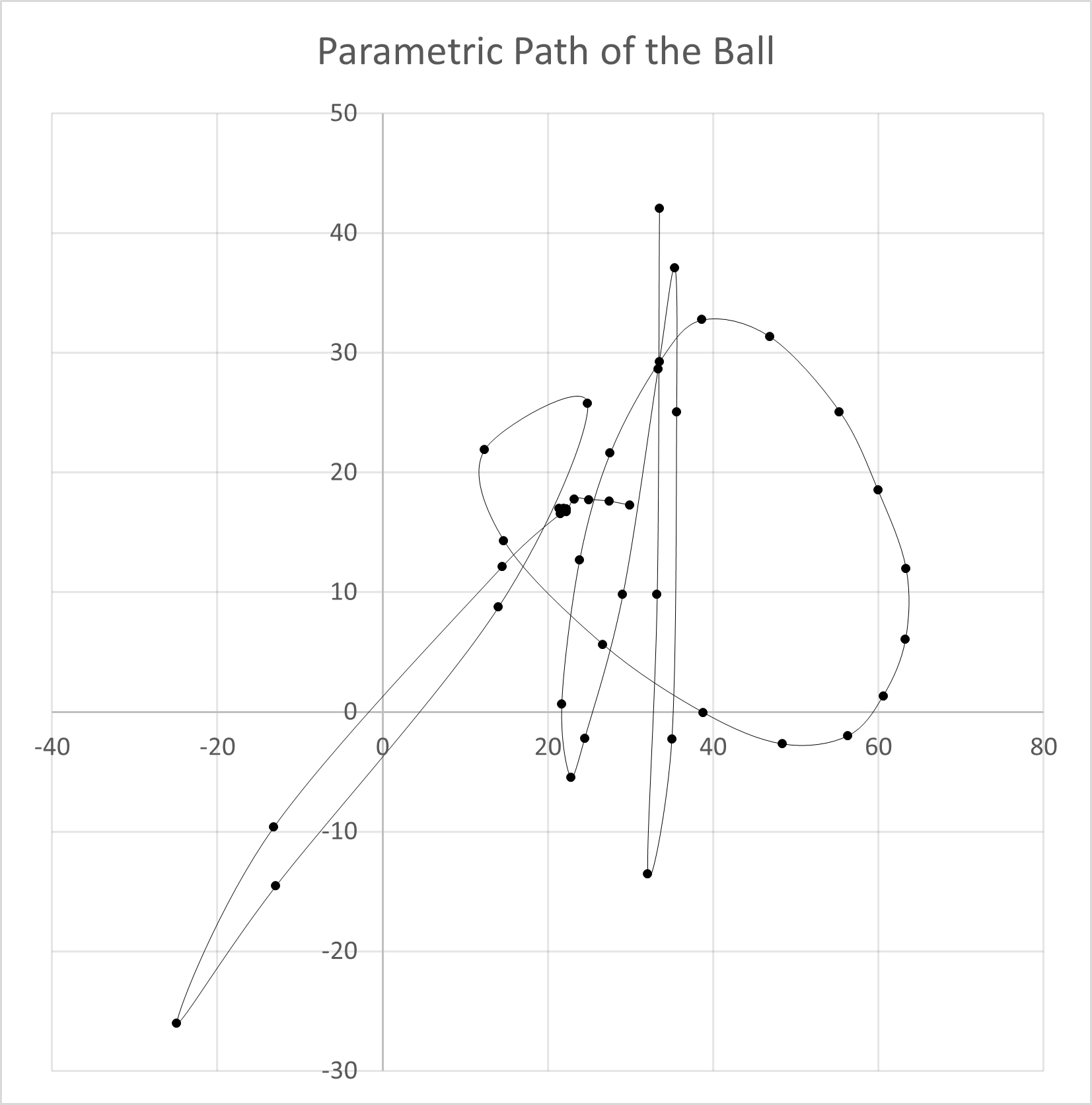
Using the program's data collection feature, we recorded some data of the system's behavior. The plot below shows the ball's position in the XY plane over time.
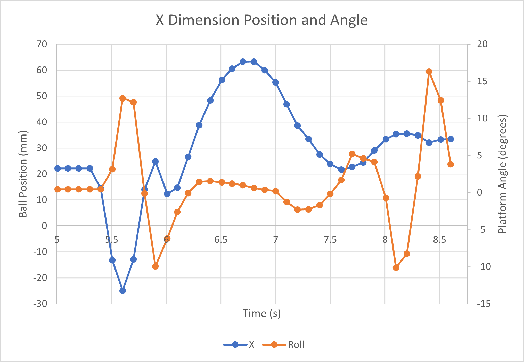
The next plot shows the platform roll angle as it tries to compensate for movement of the ball in the X direction. Consider it a 2D representation of the system.
To ensure all tasks remained focused on their explicit tasks, printing information out to the user can only be done in the taskUser task. While this is the case, it is often beneficial for other tasks to be able to communicate specific information to the user - possibly with status updates or other information they have requested. To facilitate this functionality, we created a PrintQueue class. This PrintQueue class is an implementation of the Queue class that has additional print-related functionality. The PrintQueue class consists of PrintJob objects. When these PrintJob objects are created, an optional timeout can be specified - this will remove the print job from the queue if the timeout has passed before the job is printed to the user. With this shared PrintQueue object being available to all tasks, they are able to effectively send information output to the user through the communication interface, while only having print functionality occuring in taskUser.
At the core, our controller for the final project consists of cascading PID controllers. The outer loop controller is fed ball position and must output a desired platform angle to try and get the ball in the center of the platform. The inner loop controller is fed this desired platform angle and will output motor duty cycles accordingly to get the platform in the desired orientation.
We found during testing that the most effective controller configuration had only proportional and derivative control in both the inner and outer loops. While all 4 controllers (x and y in both postiion and angle) have individually addressable gains, we found that the inner loop (platform angle) controller was able to perform effectively with the same gains. For the outer loop controllers, we found that the y axis position controller needed to have higher gains as there was less "real estate" to work with before the ball fell off the platform.
In trying to improve our controller performance, we added several optional features to the controller class. An "integral influence limit" acts as a saturation limit on the overall angle that the integral term can add to the output signal. Similarly, the "integral counter limit" limits the integral term from accumulating above and below a predermined bound, thus allowing the integral term to respond more quickly to position changes. Additionally, we tested various scalar constants and multipliers to act as stiction compensation, angle bias, and motor slip compensation, but found that these did not improve our performance above what was possible with only proportional and derivative control.
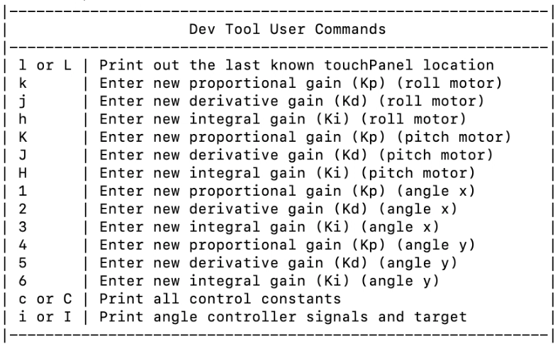
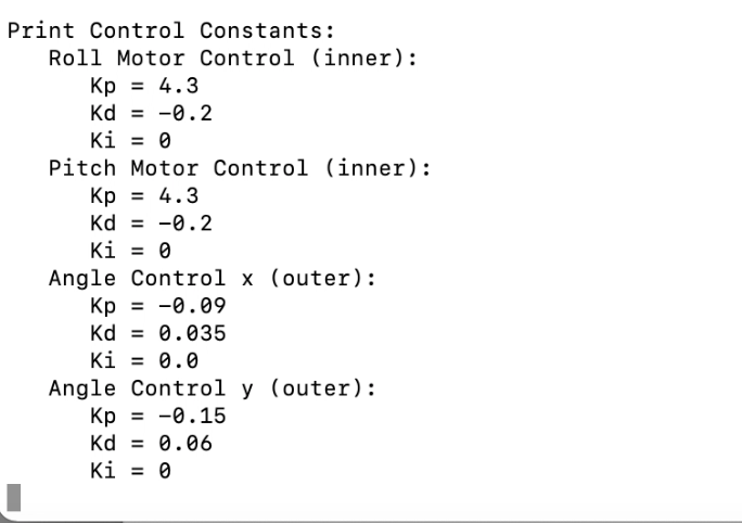
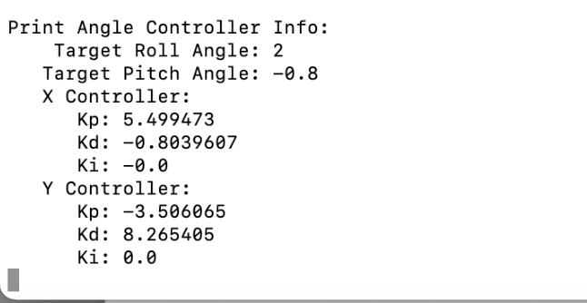
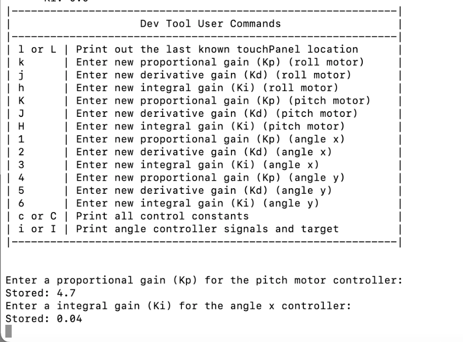
To facilitate faster tuning of the system, we implemented a developer tools menu. This allowed for direct input of each controller gain value for all four controllers. We also had a few options for printing system status, including printing the current controller gains, printing the current controller output signals, and printing last known touch panel location.
Press 'd' to list the tools:
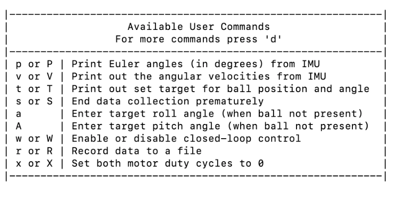
Available commands:
Print Current Controller Gains:
Print Controller Output Signals:
Enter Individual Gains:
Below is the task diagram for our final system. It is quite complex, so I would recommend looking at the pages for the respective tasks in order to learn more about what each task does.
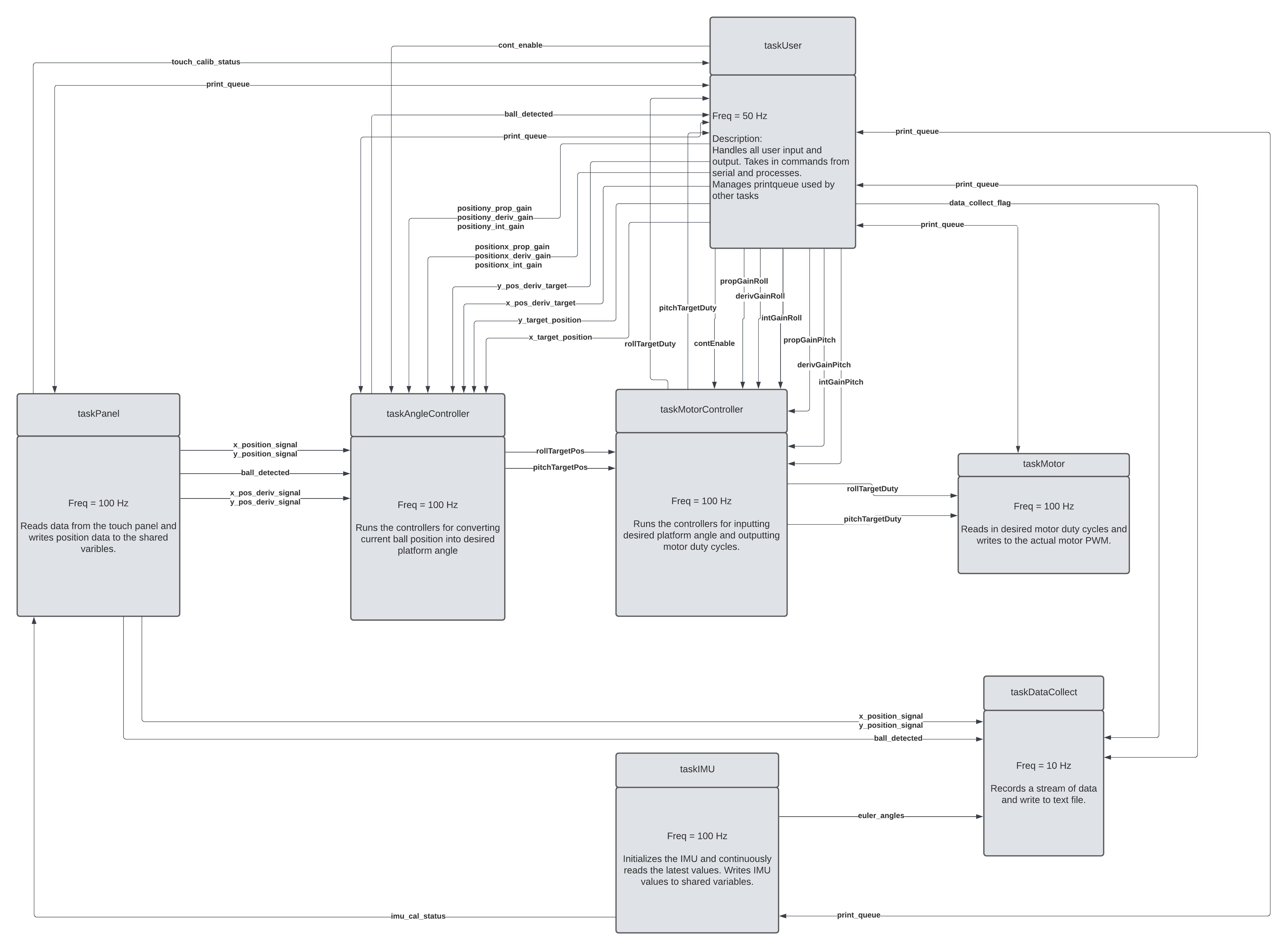
For more info, visit taskPanel.py
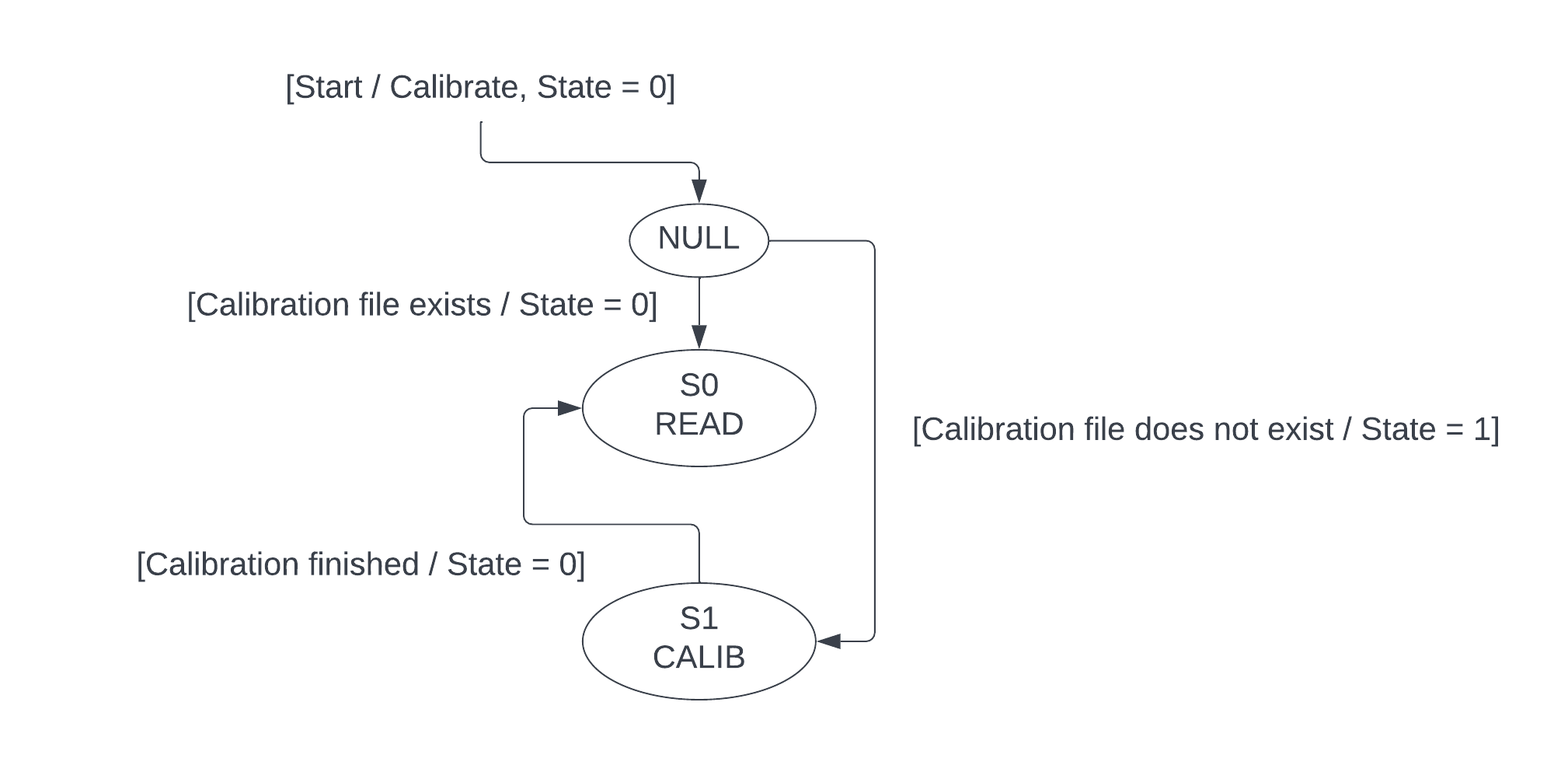
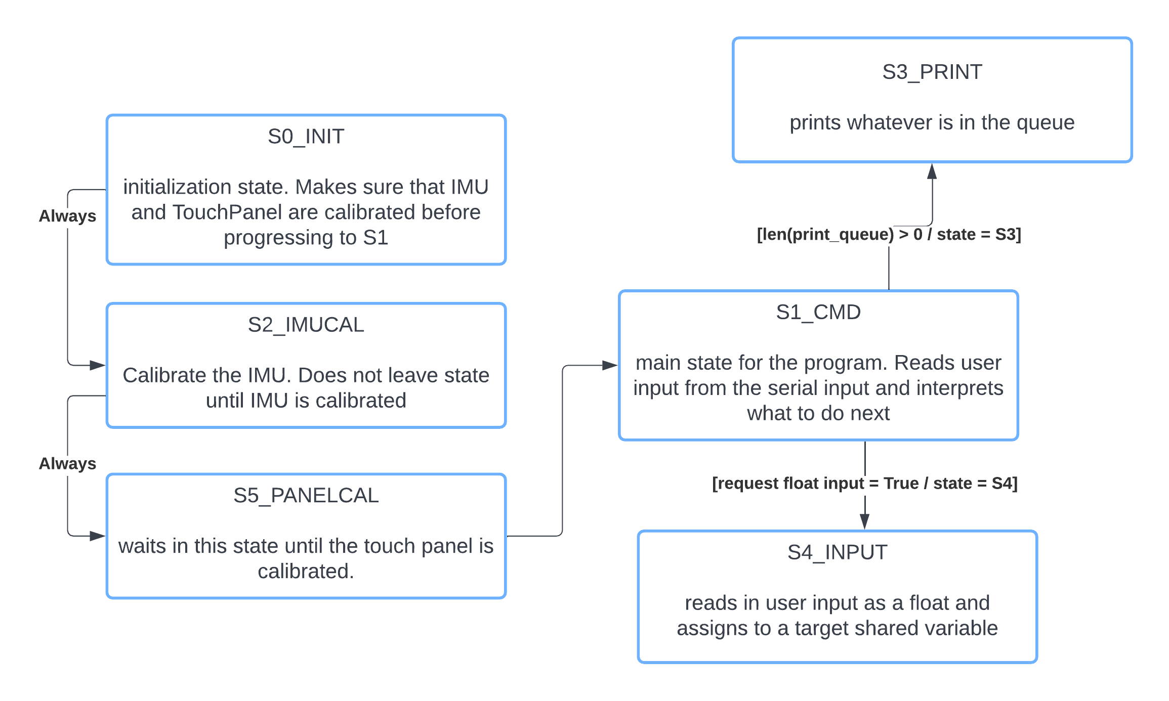
For more info, visit taskUser.py
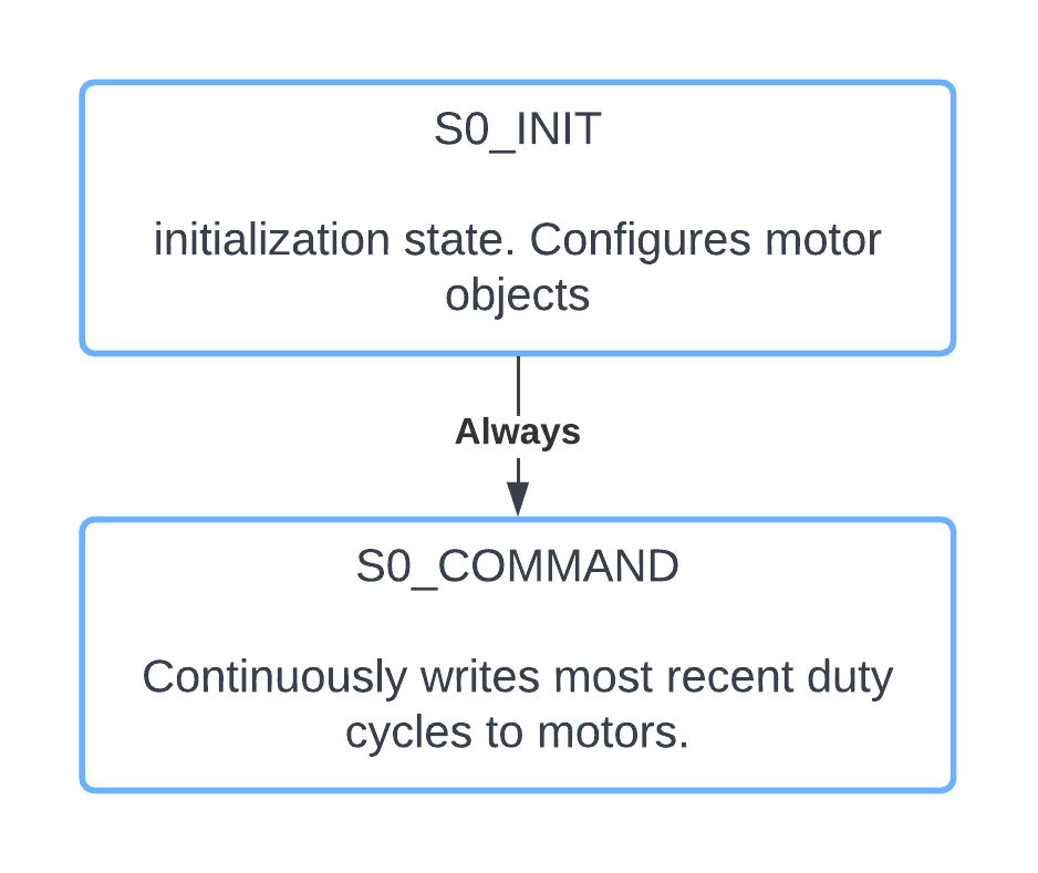
For more info, visit taskMotor.py
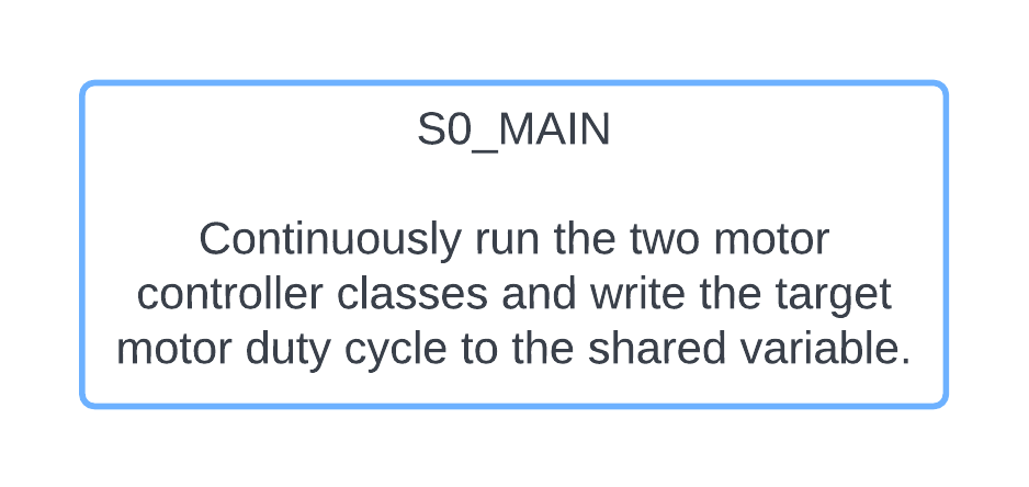
For more info, visit taskMotorController.py
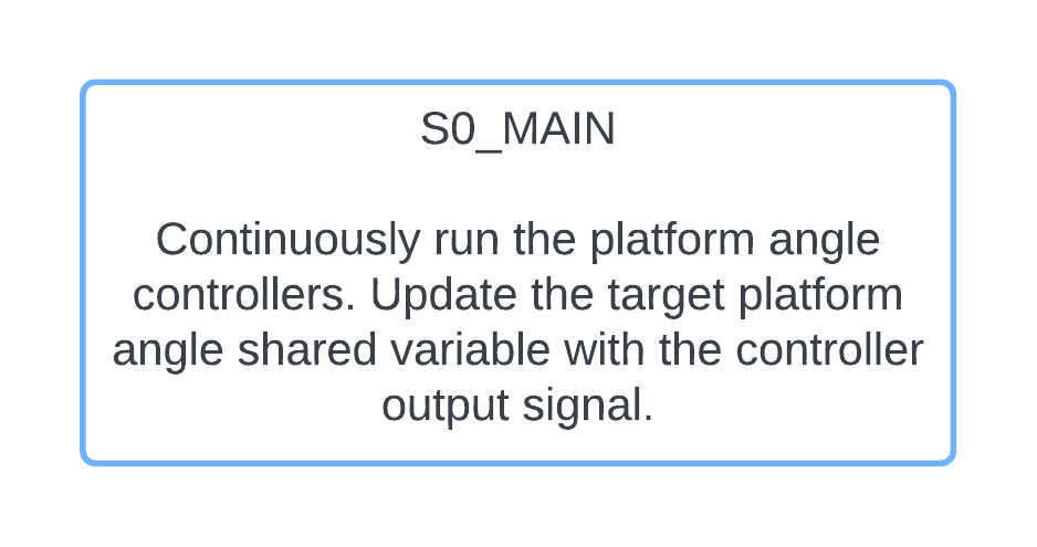
For more info, visit taskAngleController.py
For more info, visit taskIMU.py
For more info, visit taskDataCollect.py